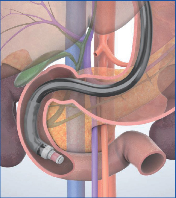
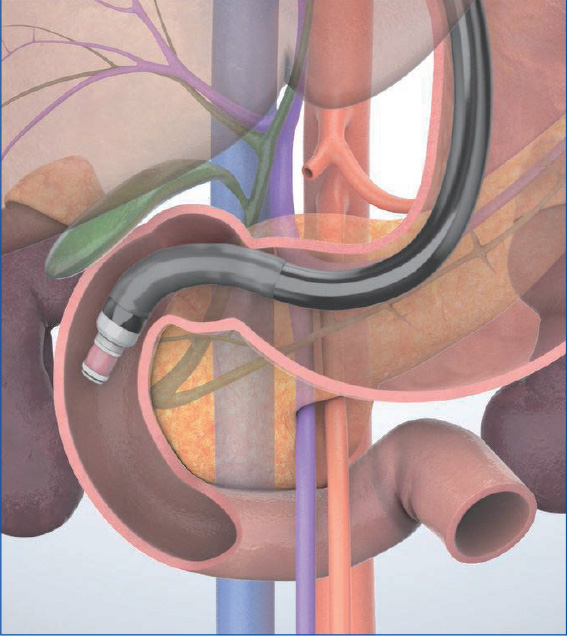
Imaging Techniques Trans-D2 (descending part of the duodenum) approach
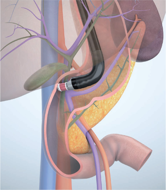
When maneuvering the scope in the descending part of the duodenum, use the “short-scope” position. Advance the scope tip as far as the inferior duodenal angle (IDA) to observe the pancreatic head, pancreatic head/body junction, bile duct, and gallbladder. Use the aorta, inferior vena cava, superior mesenteric artery/vein, and portal vein as landmarks.
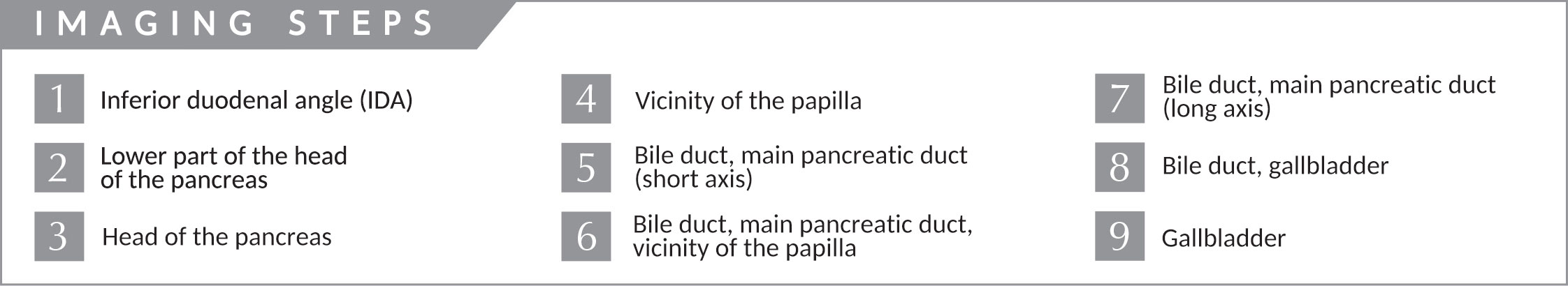
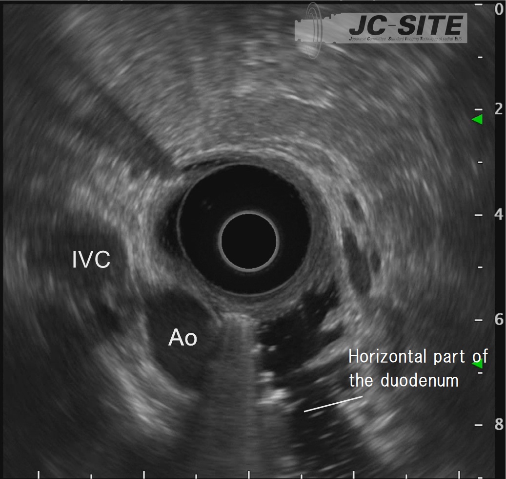
STEP 1 | Inferior duodenal angle (IDA)
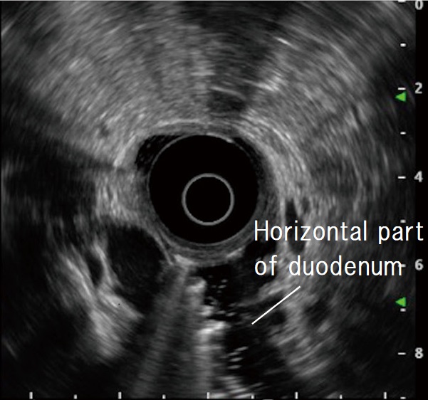
When the scope reaches the IDA, start imaging. Unless the scope tip is angulated upward, the aorta and inferior vena cava are imaged as circular cross-sections on the lower left of the screen. Instillation of water expands the lumen of the horizontal part of the duodenum, making it easier to recognize those cross-sectional images.

STEP 2 | Lower part of the head of the pancreas
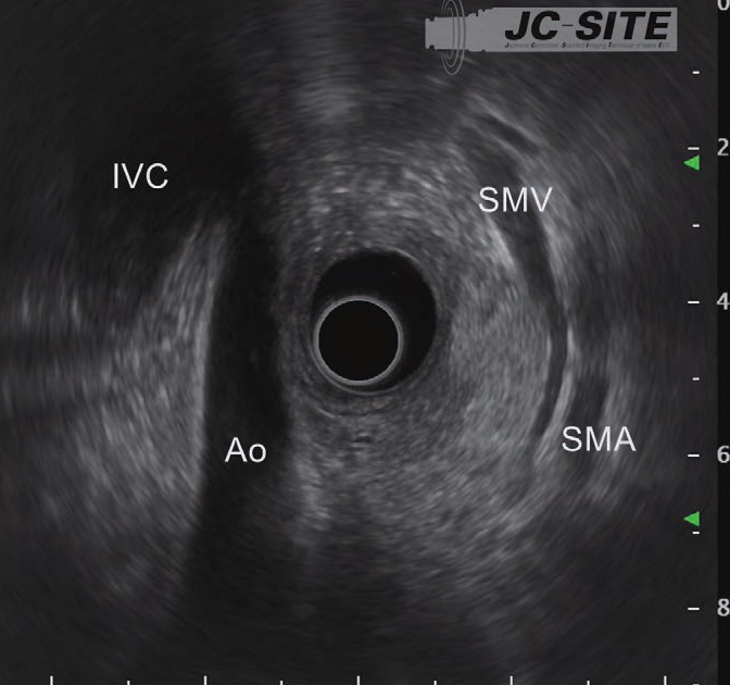
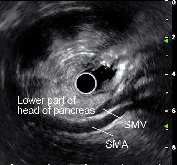
When the scope tip is deflected upward, the aorta and inferior vena cava are visualized on the left side of the screen. At this time, the superior mesenteric artery and vein are visualized on the opposite side (usually the superior mesenteric vein before on the transducer side). The head of the pancreas can now be visualized between the transducer and the superior mesenteric artery/vein. It is especially important not to miss the lower part of the head of the pancreas (see “Point ⑥”).
STEP 3 | Head of the pancreas
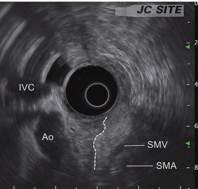
While pulling the scope slowly, decrease the up angulation to visualize the cross-sections of the aorta and the inferior vena cava. Observe the head of the pancreas positioned between the transducer and the superior mesenteric artery/vein. The high-echo area of the head of the pancreas is displayed on the right side of the screen, and the low-echo area is shown on the left (on the left side of the dashed line).
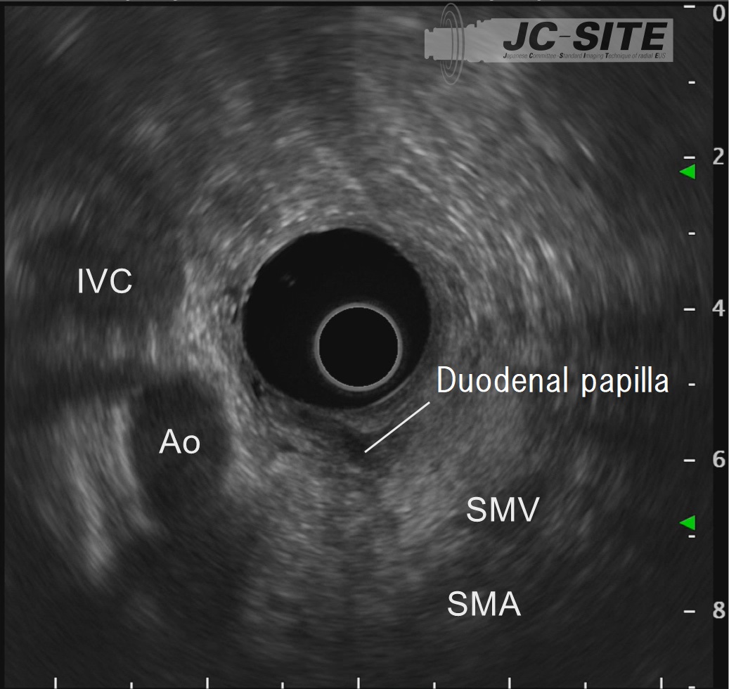
STEP 4 | Vicinity of the papilla
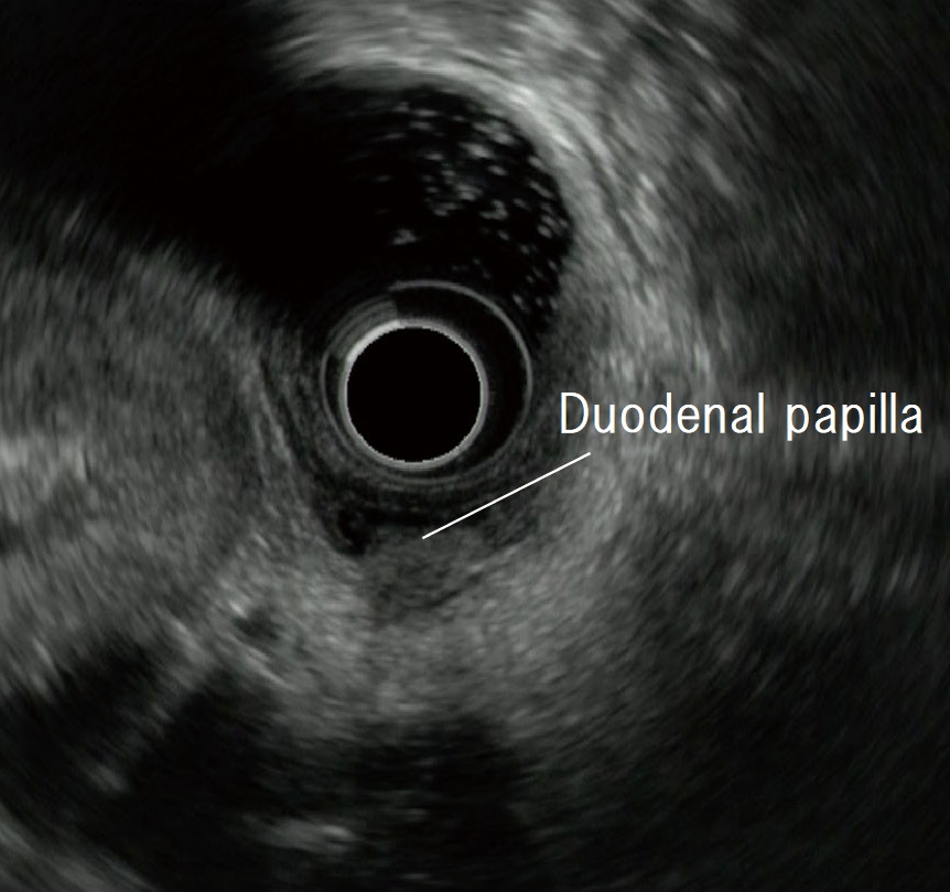
Slowly pull the scope to observe the papilla near the transducer.
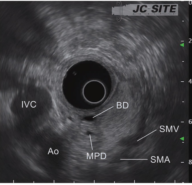
STEP 5 | Bile duct, main pancreatic duct (short axis)
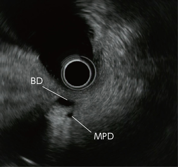
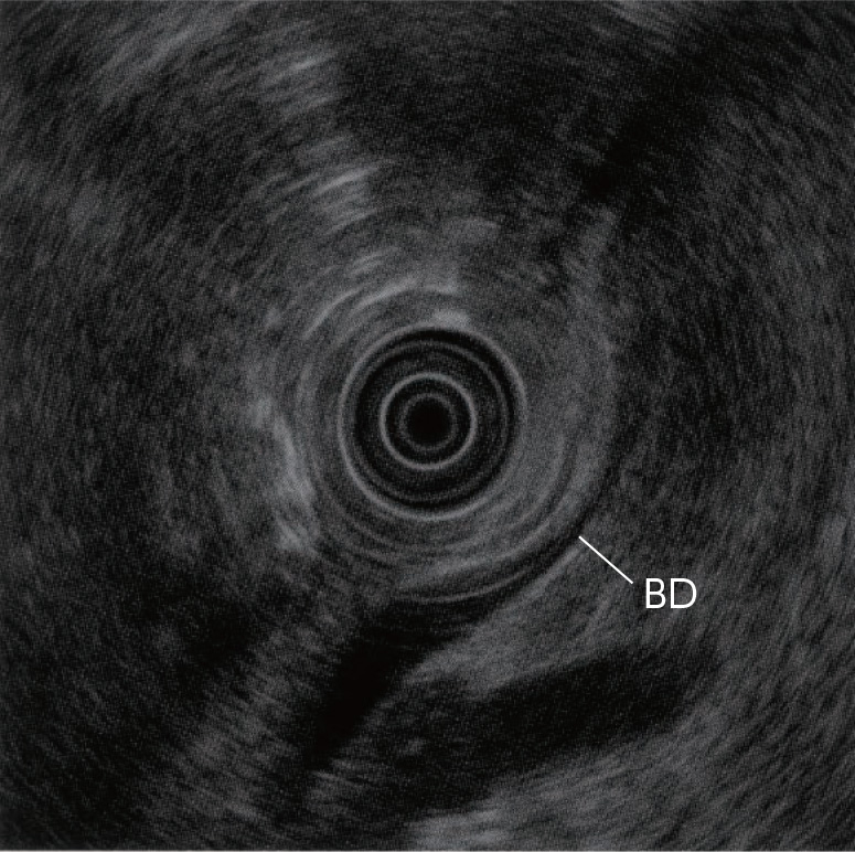
After recognizing the papilla, pull the scope slightly to image two tubular structures. The one closer to the transducer is the bile duct, and the one farther from the transducer is the main pancreatic duct.

STEP 6 | Bile duct, main pancreatic duct, vicinity of the papilla
Angulate the scope tip upward to avoid missing the bile duct and the main pancreatic duct which are currently imaged. The bile duct and the main pancreatic duct will be long-axis images. For optimal images, angulate the scope tip to the left and rotate the scope counterclockwise to fine-tune the position of the scope tip.

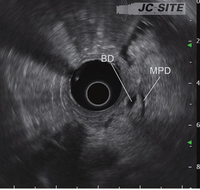
STEP 7 | Bile duct, main pancreatic duct (long axis)
While rotating the scope counterclockwise, pull it slightly to obtain long-axis images of the bile duct and the main pancreatic duct.
STEP 8 | Bile duct, gallbladder
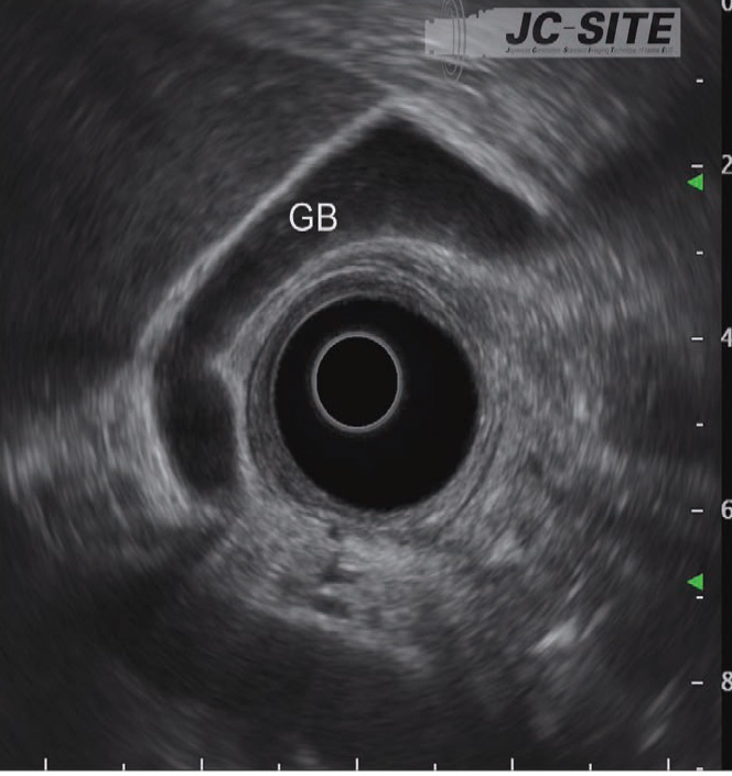
While rotating the scope counterclockwise, pull it slowly to observe the bile duct on the portal side of the liver.

STEP 9 | Gallbladder
Continue pulling the scope to observe the gallbladder from the neck to the fundus.
“Cross-sectional” and “longitudinal” imaging methods
“Standard Imaging Methods in the Pancreatobiliary Region Using Radial EUS,” which was published in 2003, introduced the “push” and “pull” methods for visualization from the descending part of the duodenum after the scope has been advanced to the IDA. It also recommended the“cross-sectional” and “longitudinal” imaging methods for observation from the lower part of the head of the pancreas when the “pull” method is used. These methods have since been refined, and in this handbook we’ve replaced the “push” method with the “long-scope” position and the “pull method with the “short-scope” position.
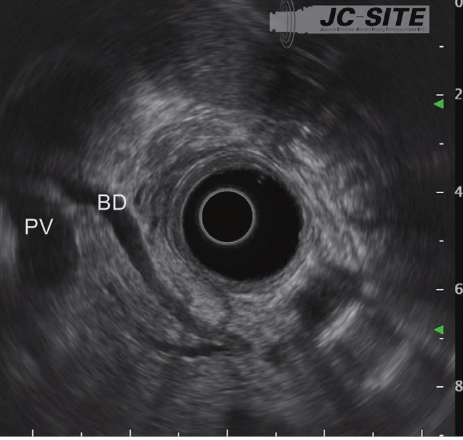
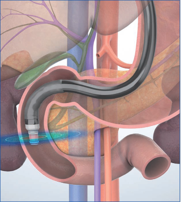
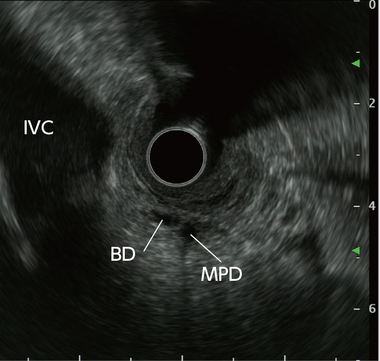
In the “cross-sectional” imaging method, scanning is performed on the plane where the scope is perpendicular to the axis of the trunk of the patient when the scope’s angulation is neutral (Figs. a, b). This is suitable for observation of the papilla as well as for the junction of the common bile duct and the main pancreatic ducts since the pancreatic and bile ducts are imaged as short-axis cross-sections. However, it is difficult to image long-axis images of the pancreatic and bile ducts.
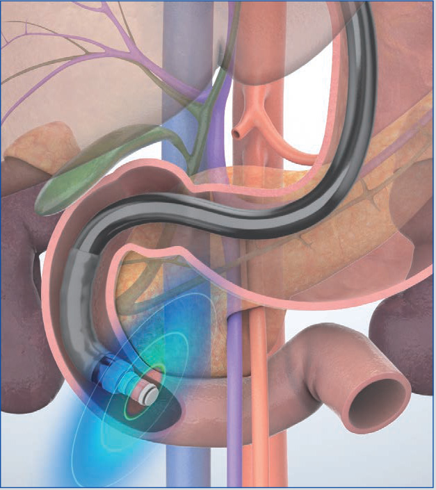
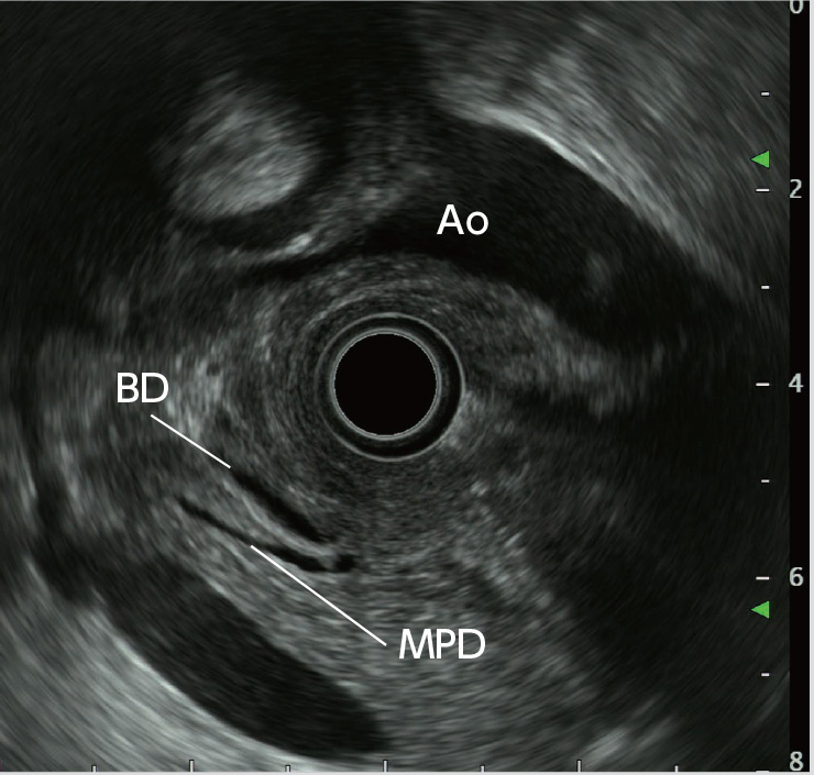
In the “longitudinal” imaging method, the scope tip is angulated upward to achieve a scanning plane that is almost parallel to the axis of the trunk of the patient. The pancreatic and bile ducts in the vicinity of the papilla are imaged in the long axis (Figs. c, d), using the aorta and the inferior vena cava visualized in the long axis as landmarks. This method makes it possible to obtain a wider view of the head and lower part of the pancreas, but may make it more difficult to identify the papilla.
In this handbook, we do not differentiate between the “cross-sectional” imaging method and the “longitudinal” imaging method. This is intentional. Instead, we recommend the following scanning method: Advance the scope as far as the IDA in the “short-scope” position. Begin by visualizing short-axis cross-sections of the pancreatic and bile ducts using the “cross-sectional” imaging method. Then angulate the scope tip upward to change those short-axis cross-sectional images to long-axis longitudinal images. This allows you to visualize the accessory pancreatic duct and a pancreaticobiliary maljunction (PBM), if present.
The scanning method recommended in this handbook for the descending part of the duodenum takes into account the importance of upward scope angulation and the ultrasound images provided by the scope when angulated upwards.
 ⑥
⑥Notes on observation of the head of the pancreas (including the uncinate process of the pancreas)
Lesions frequently occur in the head of the pancreas, so you need to observe this area very carefully. In the “long-scope” position, it is not possible to bring the scope tip as close as necessary to the distal side. Thus, it is important to be aware of the fact that you will not be able to observe the entirety of the lower part of the head of the pancreas. Furthermore, if the scope is pushed forcibly in the “long-scope” position, perforation is a very real risk. Be sure to proceed with caution.
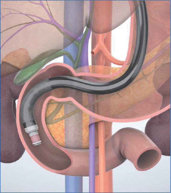
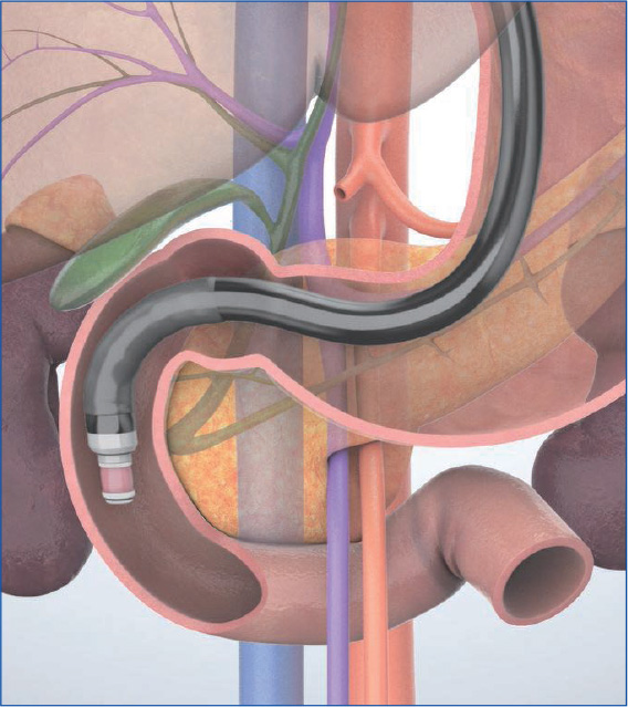
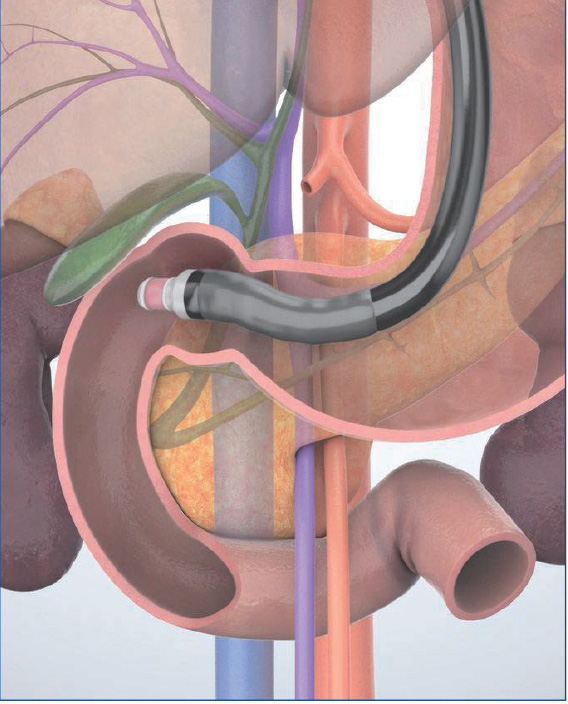
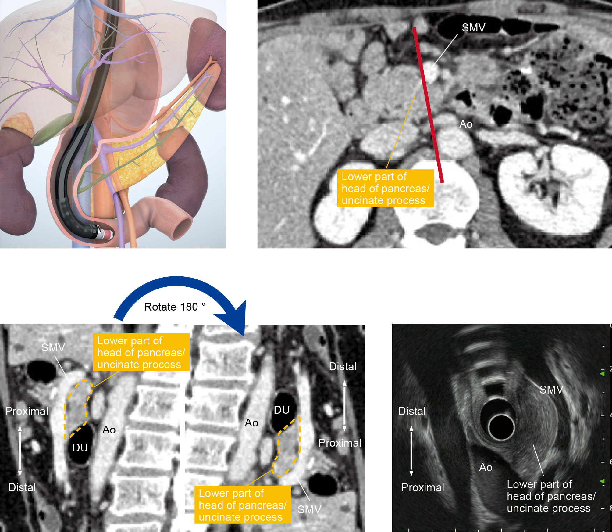
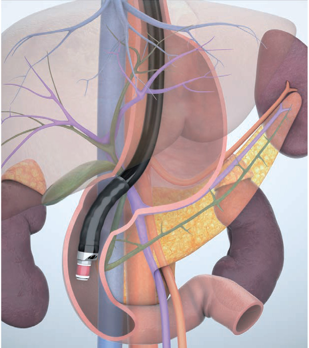
To observe the entirety of the lower part of the head of the pancreas, you will also need to use the “short-scope” position. Then image the cross-sections of the aorta and the inferior vena cava. instill lukewarm water to make it easier to recognize the horizontal part of the duodenum (Fig. a), where the head of the pancreas is located on the proximal side of the horizontal part of the duodenum . Angulate the scope tip upward to visualize the superior mesenteric artery and vein. The lower part of the head of the pancreas will be visible between the scope and the mesenteric vessels. Observe this area carefully. If possible, follow the lower part of the head of the pancreas as far as the bifurcation of the superior mesenteric vein (Fig. b).
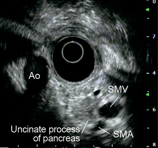
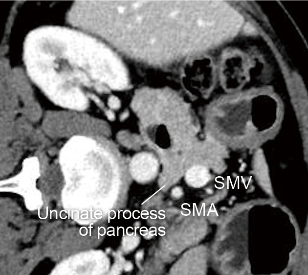
The uncinate process of the pancreas is a small part of the pancreas. It refers to the hook-like projection rising from the area between the lower part of the head of the pancreas and the left dorsal side of the superior mesenteric vein. An incisure created by the uncinate process of the pancreas projecting from the head of the pancreas is called the pancreatic notch, across which the superior mesenteric artery descends. The size of this hook-like projection varies widely from one individual to another, and may not even be noticeable in some cases. The notch is visualized using the ‘short-scope’ position in the duodenum, using the superior mesenteric artery and vein as landmarks. The uncinate process of the pancreas will be visible between the superior mesenteric artery/vein and the aorta – projecting from the head of the pancreas (Fig. c). To make it even easier to distinguish, rotate the CT image 90 degrees clockwise and compare it with the ultrasound image (Fig. d).

How to follow the pancreatic parenchyma
The pancreas is a horizontally long, narrow organ of about 20 cm in length and 2 to 4 cm in width. It is necessary to image it from both the stomach and duodenum. In order to successfully observe the entire pancreatic parenchyma using radial EUS without missing anything, there are a few points you should keep in mind. Ultrasound images are, after all, two-dimensional images. When using ultrasound images, be conscious not only of the screen’s vertical and horizontal dimensions, but also of the “depth” between the front and back. In this way, you can build a three-dimensional image, so to speak, while minimizing misses.
When observing from the stomach, use the long-axis image of the splenic vein as a landmark. Start from the body of the pancreas, which is near the transducer, and proceed to the tail of the pancreas. It is important that you follow the pancreatic parenchyma – not the vessel. Pay special attention to the distal edge of the pancreatic tail because it often veers away from the splenic vein (see “Point ④”).
When you follow the pancreatic parenchyma continuously from the duodenum, employ the “short-scope” position and bring the scope tip around the IDA. Then inflate the balloon and start the observation. Advance the scope tip as closely as possible to the distal side, and be careful not to miss any lesions in the lower part of the head of the pancreas or uncinate process (see “Point ⑥”).
Then, while continuously imaging the pancreatic parenchyma and slowly pulling the scope, the scope catches in the duodenal bulb. This means that you are in the pancreatic head-body junction, which is likely to be missed in radial EUS. To observe throughout the pancreatic head-body junction, pull the scope some more and hook the scope tip to the pylorus until the duodenum invaginates the junction in the ultrasound image. From here, deflate the balloon a little at a time and slowly pull the scope tip back to the stomach to continuously observe the body and tail of the pancreas.
Diagnosing pancreaticobiliary maljunction (PBM)
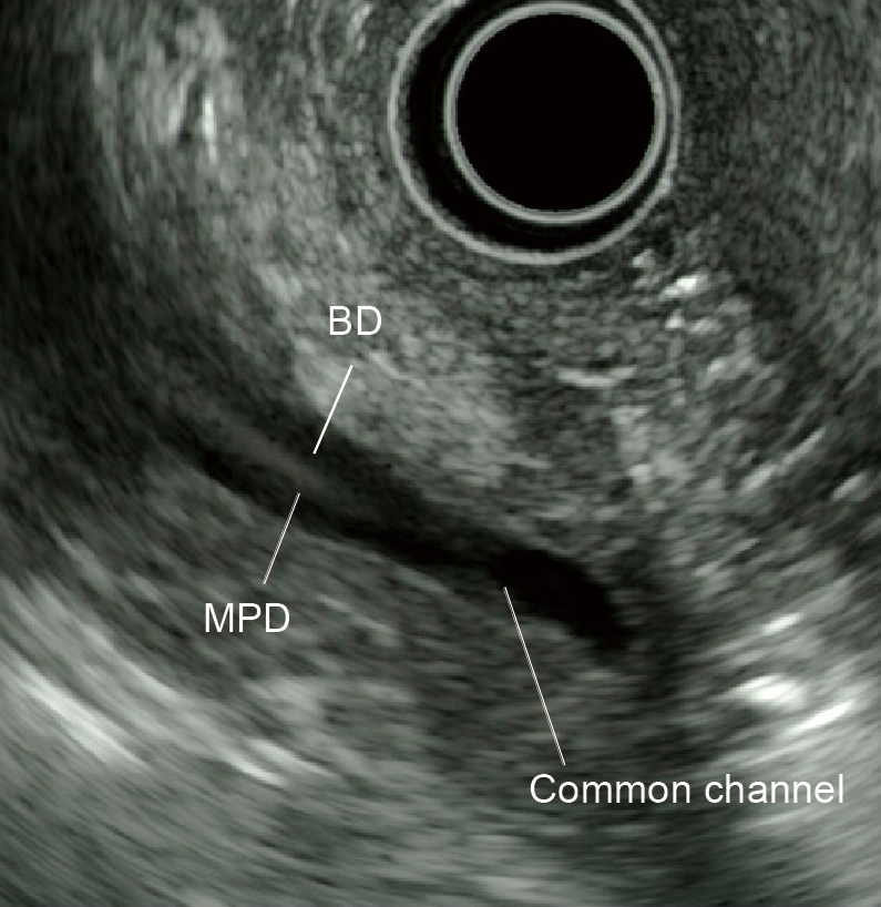
When diagnosing pancreaticobiliary maljunction (PBM), check that the pancreatic and bile ducts join outside the duodenal wall and that the sphincter of Oddi does not regulate the pancreaticobiliary junction. At the same time, confirm that an abnormally long common channel and/or an abnormal union between the pancreatic and bile ducts is evident in direct cholangiography, magnetic resonance cholangiopancreatography (MRCP), or multi-detector-row computed tomography (MDCT).
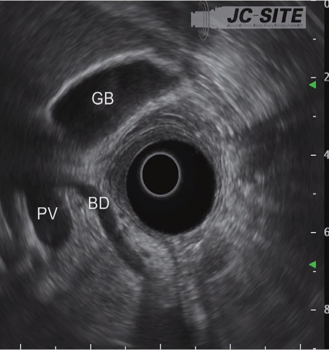
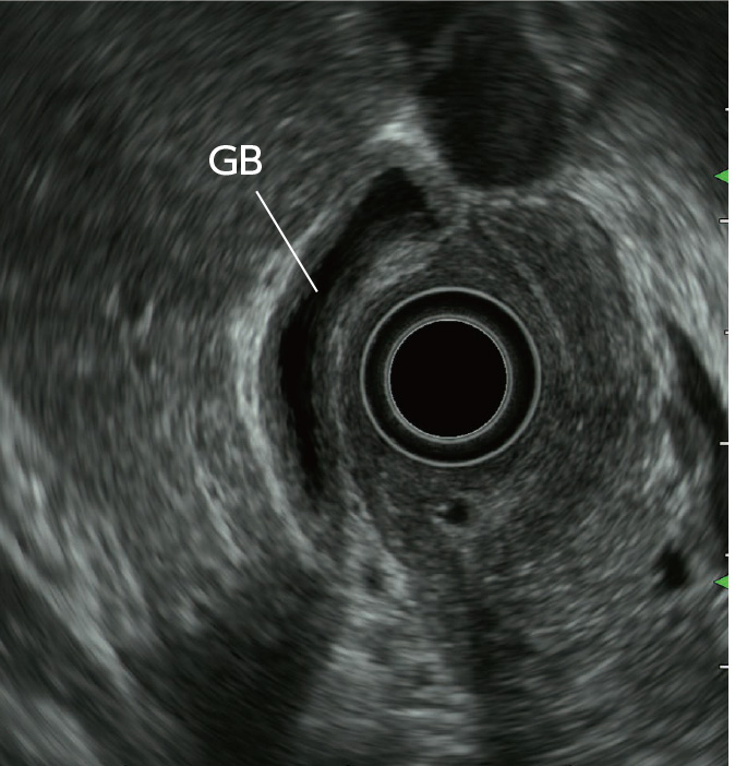
Radial EUS is helpful in detecting anatomical evidence of PBM (Fig. a) and has excellent diagnostic capability. It is relatively easy to diagnose PBM associated with bile duct dilation with EUS. On the other hand, when PBM is not associated with bile duct dilation, hyperplasia is frequently recognized in the epithelium of the gallbladder. This is often imaged as low-echo thickening inside the cystic wall via EUS and provides an important factor for diagnosis (Fig. b).
With PBM not associated with bile duct dilation, there is a high rate of occurrence of gallbladder cancer as a comorbidity. Hence, evaluation of the thickened cystic wall needs to be performed carefully, while keeping in mind that cancer may be present.

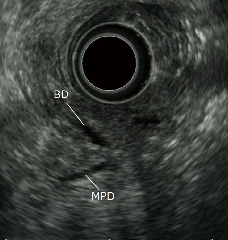
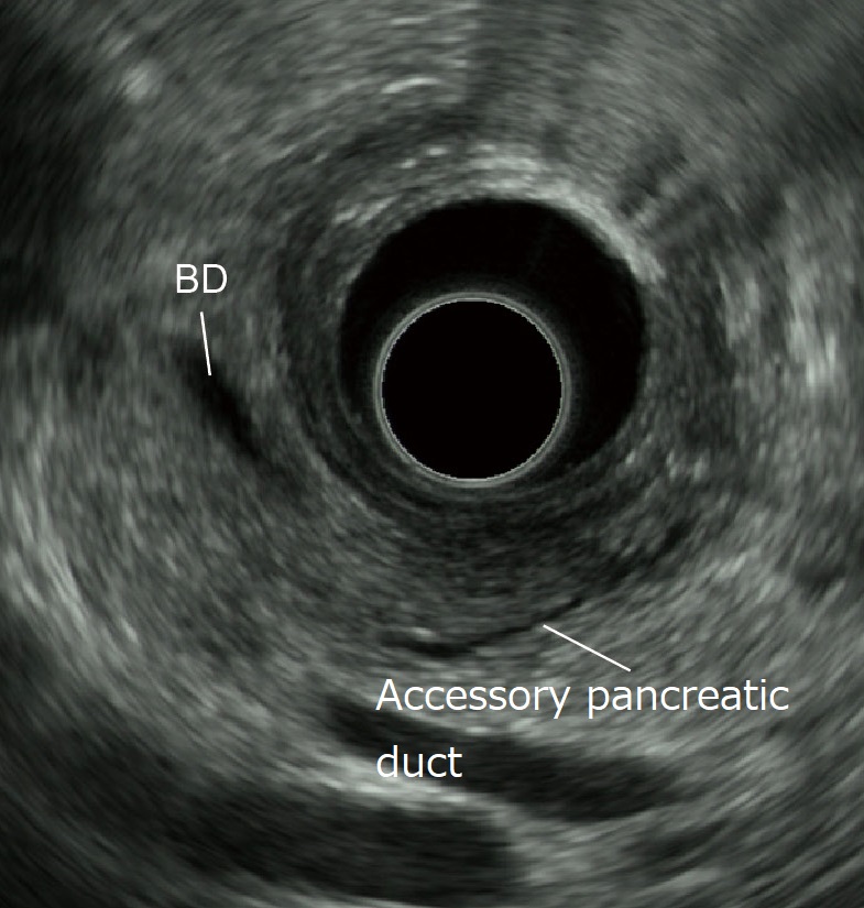
Observation of the accessory pancreatic duct
After identifying the low-echo area in the vicinity of the papilla while employing the “short-scope” position in the scanning of the descending part of the duodenum, image the bile duct and the main pancreatic duct (the duct of Wirsung) in that low-echo area (Fig. a). Then image the main pancreatic duct in a long-axis image. Subsequently, rotate the scope slightly counterclockwise to image another tubular structure (accessory pancreatic duct or the duct of Santorini) that points towards the duodenal lumen (on the transducer side) (Fig. b). Visualization of this structure may be difficult when the accessory pancreatic duct is very narrow. It can also be affected by the branching morphology. Moreover, even when the accessory pancreatic duct can be visualized, diagnosis of pancreatic duct dysraphism is often difficult. For best results, MRCP should also be used.
Understanding the anatomy when scanning in the trans-D2 (descending part of the duodenum) approach (“short-scope” position)
Below we look at the relationship between the scanned ultrasound images and the scope’s direction in the trans-D2 (descending part of the duodenum) approach (“short-scope” position) from the point of view of three scope positions.
(1) Inferior duodenal angle (IDA)
When the scope tip is angulated upward after straightening the scope in the descending part of the duodenum and is inserted as far as the IDA, the transducer points to the patient’s left. The displayed ultrasound image resembles a sagittal section viewed from the left side of the patient. Consequently, the aorta and the superior mesenteric vein are imaged in the long axis, while the lower part of the head of the pancreas and uncinate process, which are sandwiched between the aorta and superior mesenteric vein, can be visualized. The upwardly angulated scope tip is pointing to the proximal side, so the six o’clock direction corresponds to the proximal side.
(2) Horizontal section of the papilla
When observing the papilla, release the up angulation made in the IDA. Once the scope is straight, observe the papilla while pulling the scope. The aorta and the inferior vena cava are imaged in the short axis, where the horizontal section of the papilla can also be observed.
(3) Descending part of the duodenum
Angulate the scope tip upward again in the descending part of the duodenum. While pulling the scope slowly, rotate it counterclockwise. The transducer points from the anterior side to the posterior side, between the papilla and the SDA, to show the long-axis images of the portal vein and the bile duct. In this position, the direction of upward angulation often points to the proximal side. Should this be the case, the long-axis image of the bile duct is imaged on the right of the transducer on the ultrasound screen (turned 180 degrees with respect to the “long-scope” position). While you may continue observing the bile duct in this manner, you may also use the image rotation function to move the long-axis image of the bile duct to an easy-to-see position on the screen.
- Content Type